Power Door lock


#12
 11-06-2008, 09:22 PM

There are two different types of electrical tests that require a multimeter in the diagrams:
1) Continuity to ground. Switch the multimeter to measure resistance (Ohms). Touch one probe of the multimeter to the indicated terminal/cavity of the 18P connector and the other probe to a convenient metallic portion of the frame under the dash. Continuity reads on the multimeter as little or no resistance (~0 Ohms).
2) Voltage to ground. Switch the multimeter to measure DC voltage (volts). Select a range of 0-15 volts, if applicable. Touch the red probe of the multimeter to the indicated terminal/cavity of the 18P connector and the other probe to a convenient metallic portion of the frame under the dash. The voltage reading should match that indicated in the diagram. Battery voltage = ~12V.
#14
11-07-2008, 06:08 AM
No, in fact, the voltage tests require that the battery remain connected. Follow closely the directions in the diagrams.
When the voltage/resistance tests hve been completed, there is a third type of test that involves the use of jumper wires. Let us know if you have questions there as well. In fact, feel free to post any questions that come up.
When the voltage/resistance tests hve been completed, there is a third type of test that involves the use of jumper wires. Let us know if you have questions there as well. In fact, feel free to post any questions that come up.
Last edited by RonJ; 11-07-2008 at 06:48 AM.
#16
11-07-2008, 10:31 AM
Just pieces of wire several inches long with about a 1/4-inch segment of insulation removed to expose bear wire. The exposed segments are then inserted into the indicated terminals of the connector and, in so doing, serve to electrically connect the wires for those two connector terminals.
#18
11-09-2008, 02:34 PM
Don't worry, you'll figure it out. Let's start by making sure you have the multimeter set properly.
Voltage
The multimeter must be set to measure DC voltage in an appropriate range such as 0-15V. Test the multimeter using a good battery (e.g., 1.5V AA or 9V battery). Simultaneously touch the red probe to the + end and the black probe to the - end of the battery. The voltage reading should match that printed on the battery. Otherwise the mutimeter is not set correctly.
Resistance/continuity
The multimeter must be set to measure resistance in unscaled Ohms (X1). Touch the red and black probes together. The reading should jump to a 0 Ohms reading (=continuity).
#20
11-09-2008, 04:34 PM
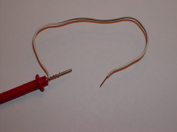
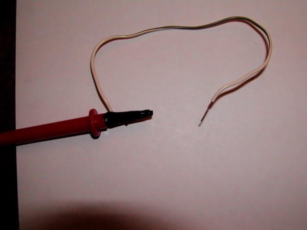
In this situation, you improvise. Tightly wind the exposed end of a wire around the metal end of each multimeter probe (see picture 1). Then tightly secure each wire with electrical tape (see picture 2). Now you can use the exposed other end of the attached wires to probe connector terminals or ground to the underdash frame.